360 Flex - Day 1 (Sunday) - Live Blogging
We just had a great breakfast at Peggy Sue’s Dinner…and moved over to the Ebay Headquarters where the conferences is about to start.
I’ll be taking notes during the day and updating this page as we go one.
UPDATE: Now that I typed all that I realized that Justin put up the slides and code on his blog: http://blog.classsoftware.com/.
Connecting Arduino Hardware to Flex: Justin Mclean
twitter: justinmclean
Justin is from Sydney, Australia.
Content:
- Arduino platform, how to program and how to connect to Flex
- 2/3 Arduino 1/3 Flex
- Hands on
So we’ll go through the followings:
- Digital Inputs
- Digital Outputs
- Analogue Inputs
- Pulse Width Modulation
- Serial Communication
- Connecting to Flex
- Review and wrap up
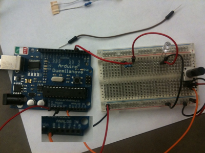
So Justin gave each attendee one board and a set of components. The board is open source hardware. I think that’s pretty cool. Feels like the hardware kit I bought for my 6 years son. The board is $25 and with all the components it’s about $40.
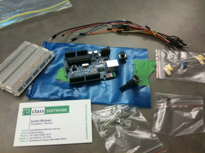
The hardware is provided to all participants by sparkfun.com
Software
http://arduino.cc/en/Main/Software
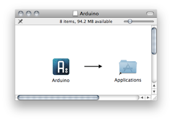
Also install the serial driver: FTDIUSBSerialDriver_10_4_10_5_10_6
Other Hardwares
- ATmega micro-controller from Atmel. It mostly runs in cars.
- Arduino Duemilanove
- Arduino Pro and Pro mini
- Lyllypad (warable)
- Funnell IO
- Mega
- Many others
ATMega328
- Hight performance low power RISC
- 16 Mzh up to 16 mips (faster as your first pc you owned – if you are a bit older)
- 32K of Memory
- SPI and 2 wire serial interfaces
- External interrupts, timers, pulse width modulation
IDE
- IDE open sourcee and cross platform.
- Based on the Processing language
- Many open source sketches (projects) and libraries availables. Ethernet library, servers, …
First Program
int ledPin = 13; // LED connected to digital pin 13
// The setup() method runs once, when the sketch starts
void setup() {
// initialize the digital pin as an output:
pinMode(ledPin, OUTPUT);
}
// the loop() method runs over and over again,
// as long as the Arduino has power
void loop()
{
digitalWrite(ledPin, HIGH); // set the LED on
delay(1000); // wait for a second
digitalWrite(ledPin, LOW); // set the LED off
delay(1000); // wait for a second
}
Now this will make the led blink:
Programming
- C like language based o wiring
- Write code and compile in IDE
- Upload compiled code using USB
- Hard to debug
Circuit Basics
- Ground and power
- Potential difference required for current ot flow
- Conductors and resistors
Digital Inputs/Outputs
- Digital pins on Arduino are dual purpose
- Digital logic and voltage on = 5V off = 0V
- Can be set to be input or output via pinMode
Variables
- boolean, char, byte, int, long, float, double, string and array
- int 16 bits, long 32 bits, float 32 bits
- Strings are nul terminated ‘\0’
- Declare by
; eg int i;
It’s actually C++…What?! At a Flex conferences :-)
Setup Function
- Used for initialization
- Run when program loaded or board reset
- Best place to place calls to pinMode
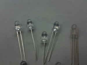
LEDs
- Current will only flow in one direction
- Longest pin connect to positive side, shortest to ground
- Dont’ connect directly to power source use in series with resistors
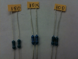
Resistors
- Resistors limit current flowing through them
- Value and tolerance indicated by cooler bands
- Resistor values for LEDs
- For RGB or LEG digits you need multiple resitors
- REG/GREEN/BLUE 180 oms, WHITE/ULTRAVIOLET 100 oms
Debugging ia Serial Port
- Use Serial.begin to set speed
- Serial.print, Serial.println to output
- Use serial monitor in IDE to view
Blinking LED
Same program that the first program but this time we just set the led to the pin 3 which is connected to the board.
Digital Inputs
- Some logic as inputs; hight 95V0 or low (0V)
- Simplest digital input switch
- Call pinMode to set as digital input as input
Connect Switch
- Wire up push button on breadboard
- Change code to turn light on/off
Now switches have three states (on, off, and in between) to the board needs to be wired to take that into account so you can program it accordingly. We added a very high resistence (10k) next to switch to ensure that the switch reports 0V when not clicked.
int led = 3;
int button = 4;
void setup() {
Serial.begin(9600);
pinMode(led, OUTPUT);
pinMode(button, INPUT);
}
void loop() {
if (digitalRead(button) == HIGH) {
Serial.println(“on”);
digitalWrite(led, HIGH);
} else {
Serial.println(“off”);
digitalWrite(led, LOW);
}
}
So let’s look at the wiring and how the switch operates:
Internal Pullup Resistors
- Set mode to input
- digitalWrite to HIGHT to turn on
- digitalWrite to LOW to turn off
So there is something like the 10K resistor built-in the board to avoid using an extra resistor on the board to make sure the switch values are on or off.
Switch Issues
- Switches can bounce and give and off values while switching
- Noise can give false results
- More a problem when switching needs to be counted
- Use timer to solve issue (time = millis())
Analog Inputs & Potentiometer
- Can read values via analogRead
- Result is in range 0 to 1023 (10 bits)
- Potentiometer is Variable resistor
- Eg Read potentiometer values with Analog Inputs
int led = 3;
int pot = 0;
void setup() {
Serial.begin(9600);
pinMode(led, OUTPUT);
}
void loop() {
int value = analogRead(pot);
digitalWrite(led, HIGH);
// Set delay based on analog input
delay(value);
digitalWrite(led, LOW);
delay(value);
}
So now when the potentiometer is turned to the right a value of 1023 is returned and the lights blinks on and off for about 1 seconds. Turning to the left makes the delay shorted (down to 0) and you can get it to run blink really fast.
LDR
- Light dependent resistor (high resistance)
- Set flash rate based on value of LDR
This is a great full day tutorial and everyone seems to have fun. It’s pretty basic, but it’s the first time I program hardware.
Now we are writing fadeIn and fadeOut functions and get the light to pulse on and off
void fadeIn(int led) {
  for (int i=0; i<256; i++) {
    analogWrite(led, i);
    delayMicroseconds(5000);
  }
}

void fadeOut(int led) {
  for (int i=255; i >= 0; i--) {
    analogWrite(led, i);
    delayMicroseconds(5000);
  }
}

void loop() {
    fadeIn(led);
    fadeOut(led);
}
Now we replace the light sensor by a temperature sensor. There are also air quality sensors, breathalyzers.
Flex
Communication between Flex and Arduinos.
- Software on Arduino (Firmata)
- USB serial to socket proxy
- Flex event based library to talk to socket (as3Glue)
Firmata is an Arduino library that support a binary protocol over serial interface. It’s Bi-directiona. Use version 2.
In the Arduino IDE let’s load the StandardFirmata program (File|Examples|Firmata|StandardFirmata). It’s a 286 lines program similar to the code we wrote so far, but more complex.
Server Proxy
From http://arduino.cc/en/Main/Software the server proxy (end of page)
To configure proxy first find what your serial device is.
In terminal do: ls /dev/cu*
/dev/cu.Bluetooth-Modem
/dev/cu.Bluetooth-PDA-Sync
/dev/cu.usbserial-A600ailA
Then add this line to your serproxy.cfg:
serial_device=/dev/cu.usbserial-A600ailA
Then we just start the server proxy:
$ ./serproxy
Serproxy – ©1999 Stefano Busti, ©2005 David A. Mellis – Waiting for clients
Now in Flex you need to add the as3glue code (http://code.google.com/p/as3glue/) then you can drive arduino as follows:
private var arduino:Arduino = new Arduino();

private function init():void {
	arduino.addEventListener(ArduinoEvent.FIRMWARE_VERSION, turnLedOn);
}

private function turnLedOn(event:ArduinoEvent):void {
	arduino.setPinMode(13, Arduino.OUTPUT);
	arduino.writeDigitalPin(13, Arduino.HIGH);
}
A qik look at the class room in the middle of coding their Flex app to drive their Arduino device:
Now we are going to write some Flex code to have some buttons that turn on/off some functions of the board.
private var arduino:Arduino = new Arduino();
private const pin:int = 3;
private const button:int = 4;


private function arduinoInit(event:Event):void {
	arduino.enableDigitalPinReporting();
	arduino.setPinMode(pin, Arduino.OUTPUT);
	arduino.setPinMode(button, Arduino.INPUT);

	arduino.addEventListener(ArduinoEvent.DIGITAL_DATA, buttonChanged);
}

private function buttonChanged(event:ArduinoEvent):void {
	if (event.pin==button) {
		event.value == Arduino.HIGH ? turnOn() : turnOff();
	}
}

private function turnOn():void {
	arduino.writeDigitalPin(pin, Arduino.HIGH);
}

private function turnOff():void {
	arduino.writeDigitalPin(pin, Arduino.LOW);
}
Thanks Justin, great talk!
Daniel Wanja
HTML5, iOS and Ruby On Rails Nouvelles Solutions, Inc.
d@n-so.com

